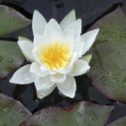
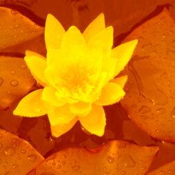
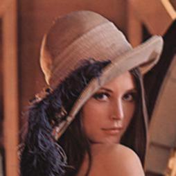
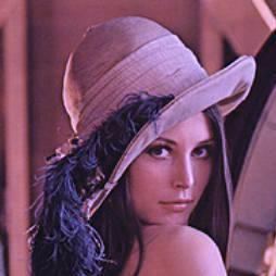
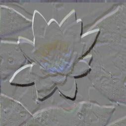
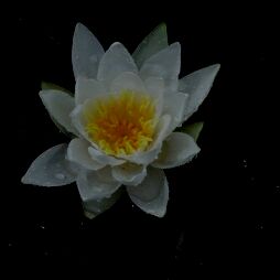
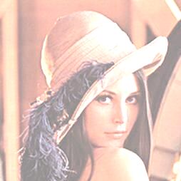
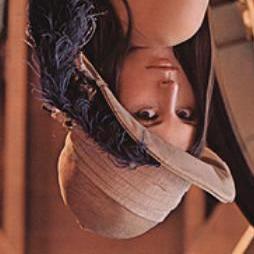
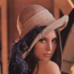
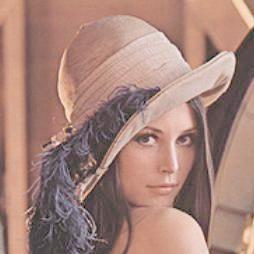
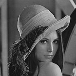
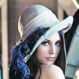
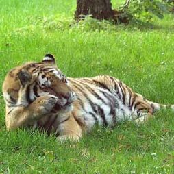
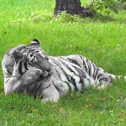
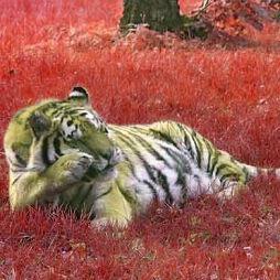
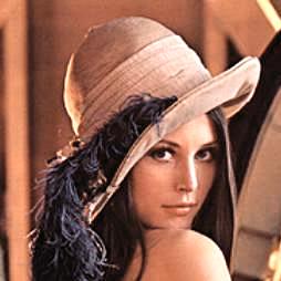
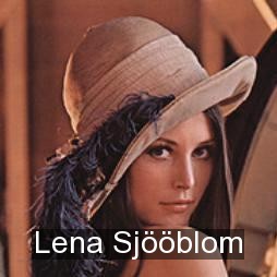
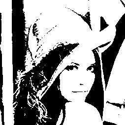
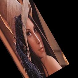
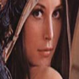
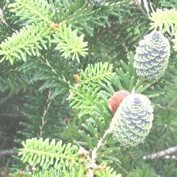
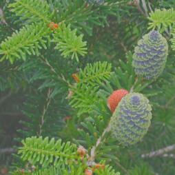
Adjusts brightness and contrast of the image [1], i.e., modifies the mean value and the variability of pixel values distribution in selected channels. It is possible to vary both brightness and contrast factors in time, thus reflecting dynamic changes in the clip. The filter can be applied either to a selection of RGB color channels [2, 3] or to the brightness channel in one of YUV and HSV color formats. Change of brightness is often useful, e.g., when processing a video filmed under extreme or changing lightning conditions. Contrast adjustment might be helpful, e.g., in scenes with very small differences between dark and bright areas.
Table 4.1. [1] original image, [2] image with enhanced brightness, [3] image with suppressed contrast
 |  |  |
The dialog allows to switch between RGB, YUV and HSV image formats and, for RGB, to choose color channels (R...red, G...green, B...blue) that will be adjusted. The RGB mode adjusts only selected RGB channels, while the other ones adjust only the intensity channel (Y in YUV or V in HSV) with no changes to image colors. There are two sliders to set the brightness and contrast parameters, the scales in percentage of parameters' impact on input image. If dynamics is set from static to dynamic, two more sliders appear in order to set brightness and contrast values at the end of the clip, with another slider affecting the rate of variation of brighness and contrast from the beginning to the end.
The following table lists the filter's parameters in network file format.
Table 4.2. Brightness and contrast parameters
| Parameter | Values | Description | Required | Default value |
|---|---|---|---|---|
| videofilter | BrightnessContrast | filter name | yes | |
| format | RGB, YUV, HSV | image format for processed frames | no | RGB |
| channel_R | boolean (0 or 1) | process red channel (RGB) | no | 1 |
| channel_G | boolean (0 or 1) | process green channel (RGB) | no | 1 |
| channel_B | boolean (0 or 1) | process blue channel (RGB) | no | 1 |
| brightness | real (-255, 255) | value added to the pixel value | no | 0 (retain brightness) |
| brightness_2 | real (-255, 255) | value added to the pixel value at the end | no | brightness (constant brightness) |
| contrast | real (-127, 127) | relative coeficient of variability of pixel values | no | 0 (retain contrast) |
| contrast_2 | real (-127, 127) | relative coeficient of variability of pixel values at the end | no | contrast (constant contrast) |
| rate | real > 0 | rate of interpolation of dynamic parameters | no | 1 (linear interpolation) |
The RGB mode operates on images in any of
RGB24, RGBA32 and
RGB32 formats. The YUV mode requests
YV12 format. This format, however, supports only images
with even dimensions so when either the width or the height is of odd
dimension, the image is opened in one of RGB formats,
broadened to even dimensions, converted to YV12 format
where brightness and contrast are modified, converted back to the
RGB format, and finally cropped to its original
dimensions. In HSV mode HSV24 format
is used.
The algorithm itself is rather straightforward. For every frame the
ratio between the dynamic parameters at the beginning and their
correspondents at the end of the clip is figured out, according to the
relative position of the frame in the clip and the rate of interpolation.
Once actual values of parameters for the processed frame are known, the
algorithm just runs through the image, and for every pixel maps its value,
in each channel that should be modified, to this value with first
brightness and then contrast modified; other channels retain their
original values. The mapping function works as follows:
map[x] = contrast_function(x + brightness), where
x = {0...255}, and the so called "contrast_function"
distributes values around MID = 128 (average pixel
value) with a variation adequate to contrast.
As to the dynamics, a dynamic parameter is
actually a couple of parameters with names like parameter_name
and parameter_name_2 (e.g., brightness
and brightness_2 is one dynamic parameter while
contrast and contrast_2 is another
one). The fist element, parameter_name, represents the
value of the dynamic parameter at the beginning of the clip whereas the
second element, parameter_name_2, represents its value
at the end. For each frame the current value of the dynamic parameter is
counted as an interpolation between the first and the second element,
according to the relative position of the frame in the clip. The rate of
interpolation can be set in parameter rate_parameter_name
(or just rate). The ratio between the first and the
second element come of ratio = (1-position) / ((1-position) +
rate*position), where position denotes the
relative position of the frame in the clip. So rate = 1
ends in a linear interpolation, while rate = 0.5 means
that the interpolation progress is slow at first and quickens gradually
(thus the ratio is 0.25 in the
middle of the clip, instead of 0.5 in linear
interpolation, for instance).
For example, brightness = -128 converts white (255)
to mid-gray (128) and all values darker than mid-gray
to black (0); contrast = 64, on the
other hand, sets values darker than dark-gray (64) to
black, values brighter than light-gray (192) to white,
while values within this range are uniformly distributed between
0 and 255. It's really useful...
Increases or decreases the brightness of RGB color channels in the image independently. This way some colors can be highlighted, while other are suppressed or remain untouched. Color balance may be quite handful, e.g., when viewing an image on a display with different color calibration than the calibration of the device the image was acquired with. Another field of usage is art photography and video processing, as different colors possess the ability to evoke specific emotions.
The dialog allows to set the contributions to each of RGB channels, their scale in percentage of maximal brightness intensity contribution. If 'dynamic' is selected, corresponding sliders appear so that the contributions' values at the end of the clip could be set; the rate slider affects the rate of interpolation of these values from the beginning to the end.
The following table lists the filter's parameters in network file format.
Table 4.4. Color balance parameters
| Parameter | Values | Description | Required | Default value |
|---|---|---|---|---|
| videofilter | ColorBalance | filter name | yes | |
| add_R | real (-255, 255) | contribution to the red channel (RGB) | no | 0 (retain values) |
| add_R_2 | real (-255, 255) | contribution to the red channel (RGB) at the end | no | 0 (constant change) |
| add_G | real (-255, 255) | contribution to the green channel (RGB) | no | 0 (retain values) |
| add_G_2 | real (-255, 255) | contribution to the green channel (RGB) at the end | no | 0 (constant change) |
| add_B | real (-255, 255) | contribution to the blue channel (RGB) | no | 0 (retain values) |
| add_B_2 | real (-255, 255) | contribution to the blue channel (RGB) at the end | no | 0 (constant change) |
| rate | real > 0 | rate of interpolation of contributions to channels | no | 1 (linear interpolation) |
The RGB mode is required, hence only
RGB24, RGBA32 and
RGB32 formats are supported.
The algorithm is simple. For every frame the ratio between the
contributions to RGB channels at the beginning (add_*)
and at the end (add_*_2) of the clip are figured out,
according to the rate parameter and the relative
position of the frame in the clip. Once actual contributions to
RGB channels for the processed frame are know, and the
frame is opened in one of supported formats, the algorithm just runs
through the image, and for every pixel maps its value in every
RGB channel to the output value. The mapping function
works for each of RGB channels as follows:
map[x] = x + add_*, where x = {0...255};
the result is cropped back to this range again, by the way.
For example, with add_R = 0, add_G = 128,
add_B = -255 white is mapped to yellow whereas black is mapped
to green, so that a vivid dichromatic image is created. Very impressive...
Convolution is a very powerful image filter - its universal algorithm enables you to perform a wide variety of transformations. It is known from image processing theory that any linear and shift-invariant transformation is in fact convolution.
Roughly speaking, every pixel in the output is computed as a weighted
sum of pixels in the neighbourhood of the corresponding input pixel. As an
example, the image below has been computed according to the formula
Out[x,y]=1/3*(In[x-1,y-1]+In[x,y]+In[x+1,y+1]), where
Out and In denote the output and input
pixels, respecitively. The result is a somewhat blurred version of the input
image (the blur goes in the diagonal direction, which is impossible to
achieve with standard blur plugins) - in fact, convolution is often used to
produce blur or sharpen effects.
Convolution operation is most easily described using the convolution matrix (also known as convolution mask) - for our example it looks like this:
The dialog lets you specify the convolution matrix. Each time you type a new value in the matrix, switch the focus to another field to apply the new value. It is possible to enter only integer (both positive and negative) values. The default matrix size 5x5 can be altered using the width and height textfields or with the arrows next to them. Make sure that you use as small matrix as possible - convolution with large matrices takes a lot of time! The convolution center is always in the center of the matrix - i.e. setting this value to 1 and all other to 0 will give an identity transformation.
You might have wondered how to enter the matrix from our example since it uses rational coefficients. The solution is to use the autoscale option, which divides the convolution result with the sum of all integers from the matrix (if nonzero). For example, convolution with mask (1 1 1) and autoscale turned on is equivalent to the convolution with mask (1/3 1/3 1/3), which never produces a value outside [0,255]. In our example you would enter the matrix shown above but with 1 on diagonal instead of 1/3. With autoscale turned off, the values greater than 255 become 255 (and the smaller than 0 become 0).
Another option, which is useful to cope with the negative values is keep sign - with this option turned on, 127 will be added to every output pixel value (see the edge detection filters for an example).
The following table lists the filter's parameters in network file format.
Table 4.7. Convolution parameters
| Parameter | Values | Description | Required | Default value |
|---|---|---|---|---|
| videofilter | Convolution | filter name | yes | |
| width | positive integer | convolution mask width | yes | |
| height | positive integer | convolution mask height | yes | |
| mask | string of whitespace-separated integers | convolution mask coefficients, exactly width*height numbers | yes | |
| autoscale | boolean (0 or 1) | turn autoscale off/on | no | 0 |
| keep_sign | boolean (0 or 1) | turn keep_sign off/on | no | 0 |
The algorithm is a straightforward implementation of the above description. The convolution plugin uses a convolution routine which is accessible to other plugins, too.
Convolution is always performed in one of the RGB modes (for each channel independently). There is an ambiguity about the convolution behaviour at the image borders (the pixels don't have all neighbours) - it is solved by repeating border pixel values.
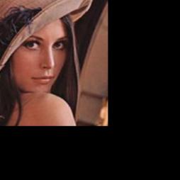
Crop filter changes the size of the image, but in contrast to Resize filter it doesn't alter the image to fit the new size, it rather cuts off the parts that won't fit or adds black borders where the image is too small. So basically what it does is creating a new viewport.
The dialog consists of two pairs of textfields; the first pair defines the top-left corner of the new viewport (relatively to the top-left corner of the original image), the second one defines width and height.
The following table lists the filter's parameters in network file format.
Table 4.9. Crop parameters
| Parameter | Values | Description | Required |
|---|---|---|---|
| x | integer | the x-coordinate of top-left corner | yes |
| y | integer | the y-coordinate of top-left corner | yes |
| width | positive integer | width of the new viewport | yes |
| height | positive integer | height of the new viewport | yes |
A colour transformation may be specified using a table of values
y = M[x], which means that every pixel with value
x is transformed into a pixel with value
M[x]. One can imagine M as a function
or a discrete curve (this is the reason for the plugin name) defined on [0,
255]. We usually deal with continuous transformations - in this case, it is
reasonable to specify only a few function values y_k = M[x_k]
and interpolate the other.
First, select the channel on which the transformation will proceed. The above example has been produced by selecting the blue channel and amplifying its highlights.
The dialog displays a sequence of sliders which represent particular
values x_k - they appear in increasing order and cover
the interval [0, 255] equidistantly from shadows to highlights. The
initial setting is the identity transformation, i.e. slider corresponding
to x_k shows the value x_k. Move the
slider up or down to increase or decrease the value M[x_k].
You can always switch back to the identity transformation by clicking the
Set defaults button.
Default type of interpolation is linear, i.e.
M is a piecewise-linear function. To produce
quantized-like images try the stairstep
interpolation, which gives piecewise-constant functions.
The following table lists the filter's parameters in network file format.
Table 4.11. Curves parameters
| Parameter | Values | Description | Required | Default values |
|---|---|---|---|---|
| videofilter | Curves | filter name | yes | |
| channel | R, G, B, Y | channel selection | yes | |
| points | positive integer | number of control points | yes | |
| curve | string of whitespace-separated integers | list of curve control points, exactly 2*points numbers | yes | |
| type | linear, stairstep | type of interpolation | no | linear |
The curve parameter allows you to specify more
general curves than the GUI dialog. It is a string in format
x_1 y_1 ... x_n y_n, where x_1 < ... <
x_n and n is the number of curve control
points (equal to the parameter points). In this way you prescribe the
values y_k = M[x_k].
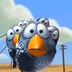
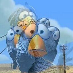
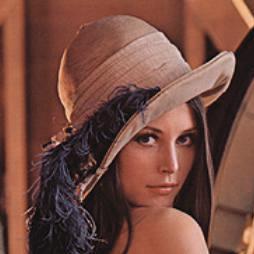
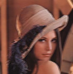
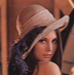
This filter attempts to remove interlacing artifacts. It was originally written by Gunnar Thalin for the VirtualDub video editor.
Table 4.12. Examples of original, interlaced and deinterlaced images
 |
 |
 |
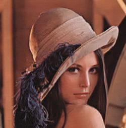 |
Blend instead of interpolate: Blending blends the interlaced lines, thus preserving more detail but producing more "blurred" image. Interpolating discards every second line and interpolates them from adjacent lines, losing detail but producing more "sharp" image (see the pictures above). Notice that none of the results is perfect and it really depends on the situation, specific data and your personal preferences which of the two methods will be better for you.
Threshold: Controls how much to deinterlace. Lower values deinterlace more.
Edge detect: It's difficult to distinguish between interlace lines and real edges (which should not be deinterlaced). This value controls this decision. Higher value leaves more edges intact.
Show deinterlaced areas only: Areas that aren't deinterlaced are greyed (with a slight transparency). Not good for pretty much anything but it looks interesting :-)
The following table lists the filter's parameters in network file format.
Table 4.13. Area-based deinterlace parameters
| Parameter | Values | Description | Required | Default |
|---|---|---|---|---|
| blend | boolean | use blending, not interpolation | no | on |
| threshold | integer | how much to deinterlace | no | 27 |
| edge_detect | integer | how hard to try to preserve edges | no | 25 |
| show_deinterlaced_area_only | boolean | self-explanatory | no | off |
| log_interlace_percent | real number | writes a list of frames with more than a given number of percent of interlaced area into a file | no | |
| log_filename | string | if you want logging, you must specify a file here | no |
This plugin implements a so-called area-based or intra-frame deinterlacing. That means that it only takes information contained in the current frame into consideration. Optimal approach would be to combine this information with inter-frame analysis, but as long as the interlacing effect isn't too heavy, the intra-frame method usually yields good-enough results.
Creates emboss of the image, a relief with slopes based on differences of intesity values, enlighted from selected direction. It is possible to use red, green and blue lights and set their positions. Thus a variety of different pictures can be created from only one image.
The dialog allows to set the relative position of red, green and blue lights, their scale in pixels. If 'common' checkbox is selected, the position of RGB lights are shared and thus only one, white light is available, creating a grayscale image. Any of RGB lights can be switched of by unchecking appropriate 'color channel' checkbox.
The following table lists the filter's parameters in network file format.
Table 4.15. Emboss parameters
| Parameter | Values | Description | Required | Default value |
|---|---|---|---|---|
| videofilter | Emboss | filter name | yes | |
| shift_x | integer (-10000, 10000) | shift of white light to the right (in pixels) | no | 0 (uniform light) |
| shift_y | integer (-10000, 10000) | shift of white light upwards (in pixels) | no | 0 (uniform light) |
| shift_R_x | integer (-10000, 10000) | shift of red light to the right (in pixels) | no | shift_x (achromatic light) |
| shift_R_y | integer (-10000, 10000) | shift of red light upwards (in pixels) | no | shift_y (achromatic light) |
| shift_G_x | integer (-10000, 10000) | shift of green light to the right (in pixels) | no | shift_x (achromatic light) |
| shift_G_y | integer (-10000, 10000) | shift of green light upwards (in pixels) | no | shift_y (achromatic light) |
| shift_B_x | integer (-10000, 10000) | shift of blue light to the right (in pixels) | no | shift_x (achromatic light) |
| shift_B_y | integer (-10000, 10000) | shift of blue light upwards (in pixels) | no | shift_y (achromatic light) |
The RGB mode is required, hence RGB24, RGBA32 and RGB32 formats are supported.
The algorithm is simple. The input image is opened in one of
supported formats (see the previous paragraph). The algorithm creates a
copy of the image in the same format for the output, runs through the
output image and for every pixel sets its value in every channel to the
average of this value and inverted value of the same pixel in the input
image shifted by shift_*_x and shift_*_y.
That is, [x,y] = [x, y]/2 + (255 - (x_in + shift_*_x, y_in +
shift_*_y))/2.
For example, shift_x = shift_y = 1 settings
produce a typical grayscale example of emboss in north-east direction. It
is a special case of convolution, isn't it?
Fades the clip in from a specified single-color canvas. The opacity of the clip at the beginning can be set as well as the rate of the fade in. It is possible to vary the color of canvas also, thus creating dynamic background. Fade in is a common filter used almost everywhere.
The dialog allows to set the opacity of the clip at the beginning (in percentage from transparent to opaque), as well as the rate of the fade process. There's a color button in order to pick the color of background. If 'dynamic' box is checked, corresponding button appears so that the background color at the end of the clip can be set; the 'rate' slider affects the rate of variation of the actual color from the beginning to the end.
The following table lists the filter's parameters in network file format.
Table 4.17. Fade in parameters
| Parameter | Values | Description | Required | Default value |
|---|---|---|---|---|
| videofilter | FadeIn | filter name | yes | |
| alpha | real (0, 1) | the transparency of canvas color (or the opacity of faded clip) at the beginning | no | 0 (fade from scratch) |
| color_R | real (0, 255) | value of the red channel (RGB) in the background color | no | 0 (black) |
| color_R_2 | real (0, 255) | value of the red channel (RGB) in the background color at the end | no | color_R (constant channel value) |
| color_G | real (0, 255) | value of the green channel (RGB) in the background color | no | 0 (black) |
| color_G_2 | real (0, 255) | value of the green channel (RGB) in the background color at the end | no | color_G (constant channel value) |
| color_B | real (0, 255) | value of the blue channel (RGB) in the background color | no | 0 (black) |
| color_B_2 | real (0, 255) | value of the blue channel (RGB) in the background color at the end | no | color_B (constant channel value) |
| rate | real > 0 | rate of fade in | no | 1 (uniform) |
| rate_color | real > 0 | rate of interpolation of background color | no | 1 (linear interpolation) |
The YUV or RGB mode is required, hence the YV12, RGB24, RGBA32 and
RGB32 formats are supported. The YV12 format, however, supports only
frames with even dimensions so when either the width or the height of the
frame are of odd dimensions, the frame is converted to the RGB24 format.
If the YUV mode is used, the color_*(_2) parameters are
converted to their corespondents in YUV.
The algorithm is not hard to understand. For every output frame the
ratio between background color at the beginning and at the end of the clip
as well as the opacity of the fading clip are figured out, according to
the rate_color and rate parameters
and the relative position of the frame. The frames is opened in one of
supported formats and then the algorithm just runs through the image and
for every pixel counts its intensity as a weighted sum of the intensy of
the infading frame and the background color, the sum being equal to one.
For example, alpha = 0.4, color_R = 255, rate_in = 0.5
settings mean that the clip is faded from less than half opaque on red
background to its full intensity with growing speed. It's not just a
simple fade in, is it?
Fades the clip out to a specified single-color canvas. The opacity of the clip at the end can be set as well as the rate of the fade out. It is possible to vary the color of canvas also, thus creating dynamic background. Fade out is a common filter used almost everywhere.
The dialog allows to set the opacity of the clip at the end (in percentage from transparent to opaque), as well as the rate of the fade process. There's a color button in order to pick the color of background. If 'dynamic' box is checked, corresponding button appears so that the background color at the beginning of the clip can be set; the 'rate' slider affects the rate of variation of the actual color from the beginning to the end.
The following table lists the filter's parameters in network file format.
Table 4.19. Fade out parameters
| Parameter | Values | Description | Required | Default value |
|---|---|---|---|---|
| videofilter | FadeIn | filter name | yes | |
| alpha | real (0, 1) | the transparency of canvas color (or the opacity of faded clip) at the end | no | 0 (fade to nothingness) |
| color_R | real (0, 255) | value of the red channel (RGB) in the background color | no | 0 (black) |
| color_R_2 | real (0, 255) | value of the red channel (RGB) in the background color at the beginning | no | color_R (constant channel value) |
| color_G | real (0, 255) | value of the green channel (RGB) in the background color | no | 0 (black) |
| color_G_2 | real (0, 255) | value of the green channel (RGB) in the background color at the beginning | no | color_G (constant channel value) |
| color_B | real (0, 255) | value of the blue channel (RGB) in the background color | no | 0 (black) |
| color_B_2 | real (0, 255) | value of the blue channel (RGB) in the background color at the beginning | no | color_B (constant channel value) |
| rate | real > 0 | rate of fade out | no | 1 (uniform) |
| rate_color | real > 0 | rate of interpolation of background color | no | 1 (linear interpolation) |
The YUV or RGB mode is required, hence the YV12, RGB24, RGBA32 and
RGB32 formats are supported. The YV12 format, however, supports only
frames with even dimensions so when either the width or the height of the
frame are of odd dimensions, the frame is converted to the RGB24 format.
If the YUV mode is used, the color_*(_2) parameters are
converted to their corespondents in YUV.
The algorithm is not hard to understand. For every output frame the
ratio between background color at the beginning and at the end of the clip
as well as the opacity of the fading clip are figured out, according to
the rate_color and rate parameters
and the relative position of the frame. The frame is opened in one of
supported formats and then the algorithm just runs through the image and
for every pixel counts its intensity as a weighted sum of the intensy of
the outfading frame and the background color, the sum being equal to one.
For example, alpha = 1.0 does not fade the clip
out at all. I must have read such a thing recently, haven't I?
This filter flips the image vertically or horizontally.
This filter has single parameter, direction of flip (either horizontal or vertical).
This filter simply blurs the input image according to the specified radius - the greater radius, the more blurred image. The name 'Gaussian' comes from the fact that the blurring is performed as a convolution with a 2D Gaussian hat function. It is possible to blur the image independently in the horizontal and vertical directions.
The dialog lets you specify the amount of blurring efect in the horizontal (mask width) and vertical (mask height) direction. Make sure you don't enter too large values - blurring then takes a lot of time!
The following table lists the filter's parameters in network file format.
Table 4.23. Gauss parameters
| Parameter | Values | Description | Required |
|---|---|---|---|
| videofilter | Gauss | filter name | yes |
| width | positive integer | blur mask width | yes |
| height | positive integer | blur mask height | yes |
As already noted, the blur plugin uses the universal convolution routine to perform the convolution with a discrete 2D Gaussian hat. The standard deviation is chosen in such a way that all nonnegligible values lie inside the specified radius. This Gaussian convolution works well in both RGB and YV12 modes.
Performs a nonlinear adjustment of image brightness, simulating the gamma calibration of displays. It is possible to vary the gamma value in time, thus reflecting dynamic changes in the clip. The filter can be applied either to a selection of RGB color channels [2] or to the brightness channel in one of YUV and HSV color formats. Gamma correction might be useful, e.g., when viewing a video filmed with a camera of a different gamma setting than the setting of the display.
The dialog allows to switch between RGB, YUV and HSV image formats and, for RGB, to choose color channels (R...red, G...green, B...blue) that will be adjusted. The RGB mode adjusts only selected RGB channels, while the other ones adjust only the intensity channel (Y in YUV or V in HSV) with no changes to image colors. There is a slider to set the relative gamma value, the scale logarithmic from 0.01 to 100.0. If dynamics is set to dynamic (not static), another slider appears in order to set the gamma value at the end of the clip; the other slider affects the rate of variation of gamma values from the beginning to the end.
The following table lists the filter's parameters in network file format.
Table 4.25. Gamma correction parameters
| Parameter | Values | Description | Required | Default value |
|---|---|---|---|---|
| videofilter | GammaCorrection | filter name | yes | |
| format | RGB, YUV, HSV | image format for filter | no | RGB |
| channel_R | boolean (0 or 1) | process red channel (RGB) | no | 1 |
| channel_G | boolean (0 or 1) | process green channel (RGB) | no | 1 |
| channel_B | boolean (0 or 1) | process blue channel (RGB) | no | 1 |
| gamma | real (0.001, 1000) | relative gamma value | no | 1 (retain gamma value) |
| gamma_2 | real (0.001, 1000) | relative gamma value | no | gamma (constant gamma value) |
| rate | real > 0 | speed of interpolation of gamma parameter | no | 1 (linear interpolation) |
The RGB mode operates on images in any of
RGB24, RGBA32 and
RGB32 formats. The YUV mode requests
YV12 format. This format, however, supports only images
with even dimensions so when either the width or the height is of odd
dimension, the image is opened in one of RGB formats,
broadened to even dimensions, converted to YV12 format
where gamma value is modified, converted back to the RGB
format, and finally cropped to its original dimensions. In
HSV mode HSV24 format is used.
The algorithm itself is rather straightforward. For every image the
ratio between the gamma value at the beginning (gamma)
and the gamma value at the end (gamma_2) of the clip,
according to the relative position of the frame and the rate of
interpolation. Once actual value of gamma for the processed frame is
known, the algorithm just runs through the image and for every pixel maps
its value, in each channel that should be processed, to this value
modified according to the gamma value; other channels retain their
original values. The mapping function works as follows:
map[x] = (x/MAX)^(1/gamma) * MAX, where x =
{0...MAX} and MAX = 255 (note: pixel values
have to be first mapped to a range 0..1, and only then
their gamma factor is corrected; afterwards, values are mapped back to
0..255).
For example, gamma = 0.5 retains both black (0)
and white (255), while mid-gray values (128)
are mapped to dark-gray (64), darkening midtones of the
image this way. Exponential...
Suppresses image colors and thus converts an image from full color to grayscale. The grayscale values can be composed from a selection of RGB color channels [2] or equal the brightness channel in either YUV or HSV color format. Grayscale is useful for image data processing in, e.g., edge detection; since RGB color channels are highly correlated and the chromacity usually carries little information, the amout of data is efficiently reduced. Another field of usage is film industry and video art as black & white projections often evoke deeper emotions.
The dialog allows to switch between RGB, YUV and HSV image formats and, for RGB, to set the percentage of RGB color channels (R...red, G...green, B...blue) that will contribute to the final grayscale value. By the way, default values equal the contributions of RGB channels to the brightness channel in YUV format. If autoscale is selected, the contributions are rescaled so that their sum is 100%.
The following table lists the filter's parameters in network file format.
Table 4.27. Grayscale parameters
| Parameter | Values | Description | Required | Default value |
|---|---|---|---|---|
| videofilter | Grayscale | filter name | yes | |
| format | RGB, YUV, HSV | image format for the computation of grayscale values | no | RGB |
| factor_R | real >= 0 | contribution of the red channel to the grayscale values (RGB) | no | 0.299 (as in YUV) |
| factor_G | real >= 0 | contribution of the green channel to the grayscale value s(RGB) | no | 0.587 (as in YUV) |
| factor_B | real >= 0 | contribution of the blue channel to the grayscale values (RGB) | no | 0.114 (as in YUV) |
| autoscale | boolean (0 or 1) | scale sum of RGB channels' contributions to 1 | no | 1 |
The RGB mode can operate on images in any of RGB24, RGBA32 and RGB32 formats. The YUV mode requests YV12 format. This format, however, supports only images with even dimensions so when either the width or the height of input image are of odd dimension, the image is opened in RGB format, broadened to even dimensions, converted to YV12 format, processed, converted to RGB format again and finally cropped to its original dimensions. In HSV mode HSV24 format is used.
The algorithm is not hard to understand. First the
format and factor_* parameters are
figured out and, if autoscale is set, balanced so that
their sum equals one. Then the image is opened in the format
specified in parameters (see the previous paragraph) and the algorithm
just runs through the image and for every pixel counts its grayscale
value. In RGB mode the grayscale value equals a weighted sum of RGB
channels' values with weights specified in factor_*
parameters. In YUV mode the chromacity channels (U and V) are set to
MID = 128 and thus the chromacity is suppressed.
Likewise, in HSV mode the saturation channel is set to 0
so that all saturation is removed. For example, factor_R = 1,
factor_G = 0 and factor_B = 0
settings extract only the red channel and display it in grayscale. More
useful than it might seem...
Flattens the image histogram, i.e. transforms intensity values in such a way that the amount of pixels with the selected intensity is approximately the same for all values. This might be useful e.g. to improve the contrast of an overexposed or underexposed image.
The dialog allows you to switch between RGB and grayscale modes. The former equalizes each of RGB channels, the latter equalizes only intensity channel.
The following table lists the filter's parameters in network file format.
Table 4.29. HistEq parameters
| Parameter | Values | Description | Required |
|---|---|---|---|
| videofilter | HistEq | filter name | yes |
| channel | rgb, gray | which channels to equalize | yes |
The grayscale mode operates on YV12 images, otherwise RGB24 is used.
The algorithm first computes the image histogram, i.e. a vector
Hist[x] = number of pixels with intensity
x. Suppose our image consists of w*h
pixels and the intensities run from 0 to 255. The desired transformation
x -> Map[x] is then computed according to the
formula Map[x]=255*(Hist[0]+...+Hist[x])/(w*h). This
procedure is reasonably fast and gives a good approximation to an ideally
flat histogram.
Restricts the range of hues in image - colors outside this range fade to gray. This way some colors may completely disappear while other remain untouched. Hue restriction is able to create amazing effects, especially when you want to highlight an object of a unique color within the image. Therefore it can be effectively used, e.g., in television broadcast, music videos or photography art.
The dialog allows to set the bounds of a periodic color spectra with the period of 360 degrees; pixels with the hue channel outside this range will fade to gray. If 'dynamic' is selected, bounds at the end of the clip can be set; the rate parameter affects the rate of interpolation between corresponding bounds from the beginning to the end.
The following table lists the filter's parameters in network file format.
Table 4.31. Hue restriction parameters
| Parameter | Values | Description | Required | Default value |
|---|---|---|---|---|
| videofilter | HueResctriction | filter name | yes | |
| hue_min | real (-360, 360) | lower bound of color spectra (in degrees) | no | -360 (no restriction) |
| hue_min_2 | real (-360, 360) | lower bound of color spectra (in degrees) at the end | no | hue_min (constant restriction) |
| hue_max | real (-360, 360) | upper bound color spectra (in degrees) | no | 360 (no restriction) |
| hue_max_2 | real (-360, 360) | upper bound of color specta (in degrees) at the end | no | hue_max (constant restriction) |
| rate | real > 0 | speed of the interpolation of both bounds | no | 1 (linear interpolation) |
The HSV mode is required, hence only the HSV24 format is supported.
The algorithm is simple. For every image the ratio between the lower
and upper bounds at the beginning (hue_min and
hue_max) and at the end (hue_min_2
and hue_max_2) of the clip are figured out, according
to the rate parameter and the relative position of the
frame. Once the actual bounds are figured out, the image is opened in HSV
format (see the previous paragraph) and the algorithm just runs through
the image and for every pixel tests whether its value in the hue channel
lies within the range of the actual borders. If not, the saturation of the
pixel is set to zero - chromacity is suppressed and pixel becomes gray.
For example, if hue_min = -60 (magenta) and
hue_max = 180 (cyan), bluish colors fade to gray while
all colors from magenta across red, yellow and green to cyan remain.
Wow...
Adjusts hue, saturation and brightness characteristics of image - increases or decreases the saturation and brightness of pixels and shifts or inverts their color spectra. This way one color may turn into a completely different one or even fade to gray. Hue and saturation can create wonderful effects, some of them frequently used in modern art and photography (think of Warhol).
The dialog allows to shift a periodic color spectra with the period of 360 degrees, and contribute to saturation (from grayscale to full-color) and value (from dark to light) characteristics of pixels in HSV format, the scale in percentage of maximal contribution. If 'invert' is selected, the color spectrum is first flipped around 0 (red color) and only then shifted. If 'dynamic' is selected, hue, saturation and value parameters at the end of the clip can be set; the rate parameter affects the rate of interpolation between corresponding parameters from the beginning to the end.
The following table lists the filter's parameters in network file format.
Table 4.33. Hue and saturation parameters
| Parameter | Values | Description | Required | Default value |
|---|---|---|---|---|
| videofilter | HueSaturation | filter name | yes | |
| hue | real (-360, 360) | color spectrum shift (in degrees) | no | 0 (retain hue) |
| hue_2 | real (-360, 360) | color spectrum shift (in degrees) at the end | no | 0 (constant change) |
| saturation | real (-255, 255) | change of saturation (from grayscale to full-color) | no | 0 (retain saturation) |
| saturation_2 | real (-255, 255) | change of saturation (from grayscale to full-color) at the end | no | 0 (constant change) |
| value | real (-255, 255) | change of brightness (from dark to light) | no | 0 (retain value) |
| value_2 | real (-255, 255) | change of brightness (from dark to light) at the end | no | 0 (constant change) |
| invert | boolean (0 or 1) | flip color spectra (hue) | no | 0 |
| rate | real > 0 | speed of the interpolation of parameters | no | 1 (linear interpolation) |
The HSV mode is required, hence only the HSV24 format is supported.
The algorithm is simple. For every image the ratio between the
contributions to HSV channels at the beginning (hue,
saturation and value) and at the end
(hue_2, saturation_2 and
value_2) of the clip are figured out, according to the
rate parameter and the relative position of the frame.
Once the actual contributions are figured out the image is opened in HSV
format (see the previous paragraph) and the algorithm just runs through
the image and for every pixel map its value in every HSV channel to the
output value. The mappings work as follows: map_hue[x] = x + hue
(or map_hue[x] = - x + hue for invert = 1),
where x = {0...359}; map_saturation[x] = x +
saturation, where x = {0...255};
map_value[x] = x + value, where x = {0...255}.
If needed, the results are cropped back to their ranges.
For example, when hue = 60, red is mapped to
yellow, green to cyan and blue to magenta; on the other other hand, if
hue = 0 and invert = 1 in addition,
red color remains while green is mapped to blue and vice versa. Awesome,
isn't it?
Inverts brightness of the image [1], i.e., for every pixel inverts its value in each of selected channels. The filter can be applied either to a selection of RGB color channels [2] or to the brightness channel in one of YUV [3] and HSV color formats. This might be useful, e.g., when a scanned negativ of a photography (X-ray picture, for instance) should be converted to a digital image of its positive (print).
Table 4.34. [1] original image, [2] image with RGB channels inverted, [3] image with Y channel inverted
 | 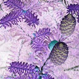 | 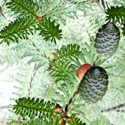 |
The dialog allows to switch between RGB, YUV and HSV format and, for RGB, to choose color channels (R...red, G...green, B...blue) that should be inverted. The RGB format inverts selected RGB channels, while the other ones invert only intensity channel (Y in YUV or V in HSV) and thus preserve image colors (see pictures).
The following table lists the filter's parameters in network file format.
Table 4.35. Invert parameters
| Parameter | Values | Description | Required | Default value |
|---|---|---|---|---|
| videofilter | Invert | filter name | yes | |
| format | RGB, YUV, HSV | image format for processed frames | no | RGB |
| channel_R | boolean (0 or 1) | invert red channel (RGB) | no | 1 |
| channel_G | boolean (0 or 1) | invert green channel (RGB) | no | 1 |
| channel_B | boolean (0 or 1) | invert blue channel (RGB) | no | 1 |
The RGB mode operates on images in any of
RGB24, RGBA32 and
RGB32 formats. The YUV mode requests
YV12 format. This format, however, supports only images
with even dimensions so when either the width or the height is of odd
dimension, the image is opened in one of RGB formats,
broadened to even dimensions, converted to YV12 format,
inverted, converted back to the RGB format, and finally
cropped to its original dimensions. In HSV mode
HSV24 format is used.
The algorithm itself is quite simple - it just runs through every
image and for every pixel maps its value, in each channel that should be
processed, to this value inverted; other channels retain their original
values. The mapping function works as follows: map[x] = MAX - x,
where x = {0...255} and MAX = 255.
Quick and simple, yet impressive...
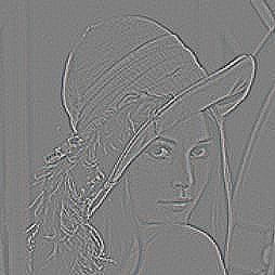
This filter attemps to find edges in the input image. It detects edges going in all directions. (See also the Sobel edge detection filter.)
The dialog has a single option called keep sign; it produces images which look like contours embossed in a piece of metal (see the above example). With keep sign turned off you get bright contours on a dark background.
The following table lists the filter's parameters in network file format.
Table 4.37. Laplace parameters
| Parameter | Values | Description | Required | Default value |
|---|---|---|---|---|
| videofilter | Laplace | filter name | yes | |
| keep_sign | boolean (0 or 1) | turn keep_sign off/on | no | 0 |
Laplace edge detection is based on a convolution with the following mask:
Note that this is a discrete approximation of a differential operator known from analysis; it measures the rate of change of a function at a point.
The meaning of keep sign option is the same as with convolution plugin - with this option turned on, 127 will be added to every output pixel value; otherwise absolute values are used.
This filter interpolates intensity values from a given input range
[min_in, max_in] to a specified output range
[min_out, max_out]. Values smaller than
min_in become min_out, those greater
than max_in become max_out.
You might boost the contrast of a specific range of intensities (e.g.
shadows or highlights) by spreading it over a wider range of values. For an
example see the image below, which shows the result after mapping the
intensity values from [0, 200] to [0, 255].
The dialog lets you choose which channel to transform. Then specify the input and output ranges using the keyboard or clicking on the arrows next to the textfields. Every time you type a new value, switch the focus to another textfield to apply the new value.
The following table lists the filter's parameters in network file format.
Table 4.40. Levels parameters
| Parameter | Values | Description | Required |
|---|---|---|---|
| videofilter | Levels | filter name | yes |
| channel | R, G, B, Y | which channel to process | yes |
| min_in, max_in | integer 0 - 255, min_in<max_in | input range specification | yes |
| min_out, max_out | integer 0 - 255, min_out<max_out | output range specification | yes |
Blurs the clip in time. This way moving objects blur while static remain relatively sharp. It is possible to set different width of blur for each of RGB channels thus creating surprising effects. Also, different width of blur and different decay of distant preceding and following frames can be set, thus blurring more with the previous than with the following scenes or vice versa. Motion blur can be used to emphasize motions, simulate light traces, or soften some scenes as with motion blur they seem more still.
The dialog allows to set the number of preceding as well as the number of following frames in motion blur for each of RGB channels; when 'common' box is checked, they are shared by all channels and the sliders move simultaneously. It is also available to set the decay of distant frames contribution to the result of motion blur for both past and future.
The following table lists the filter's parameters in network file format.
Table 4.42. Motion blur parameters
| Parameter | Values | Description | Required | Default value |
|---|---|---|---|---|
| videofilter | MotionBlur | filter name | yes | |
| decay_in | real > 0 | rate of decay of preceding frames | no | 1 (linear decay) |
| decay_out | real > 0 | rate of decay of following frames | no | 1 (linear decay) |
| frames_in | integer (1, 100) | default number of preceding frames in motion blur | no | 1 (no blur) |
| frames_out | integer (1, 100) | default number of following frames in motion blur | no | 1 (no blur) |
| frames_R_in | integer (1, 100) | number of preceding frames in motion blur of red channel (RGB) | no | frames_in (same as other channels) |
| frames_R_out | integer (1, 100) | number of following frames in motion blur of red channel (RGB) | no | frames_out (same as other channels) |
| frames_G_in | integer (1, 100) | number of preceding frames in motion blur of green channel (RGB) | no | frames_in (same as other channels) |
| frames_G_out | integer (1, 100) | number of following frames in motion blur of green channel (RGB) | no | frames_out (same as other channels) |
| frames_B_in | integer (1, 100) | number of preceding frames in motion blur of blue channel (RGB) | no | frames_in (same as other channels) |
| frames_B_out | integer (1, 100) | number of following frames in motion blur of blue channel (RGB) | no | frames_out (same as other channels) |
The YUV or RGB mode is required, hence the YV12, RGB24, RGBA32 and RGB32 formats are supported. The YV12 format, however, supports only frames with even dimensions so when either the width or the height of the frame are of odd dimensions, the image is converted to the RGB24 format. Anyway, the YUV mode is available only when the width of blur is common to all channels.
The algorithm may be implemented in more ways; this is one of those
which support frame preview but might be a little slower during rendering.
For every frame the number of preceding and following frames that will be
required is figured out according to the maxima of frame_*_in
and frame_*_out parameters and the position of the
frame. Once these frames are available they are all opened in one of
supported formats (see previous paragraph). The algorithm just runs
through the frames and for every pixel counts its value in each of RGB
channels (or even YUV, for common width of blur) as a weighted sum of
pixel values in preceding frames of this channel plus a weighted sum of
pixel values in following frames of the channel; the two sums together are
equal to one. The weight of a frame descends as the frame is further from
the actual one, the rate of decay depending on decay_in
parameter for preceding frames and on decay_out for
following frames.
For example, frame_in = 25, frame_out = 50, decay_in = 2.0,
decay_out = 0.5 settings usually leave slight, up to one second
traces of the preceding scenes and significant, up to two seconds traces
of the following scenes. On the other hand, setting of, e.g.,frame_R_in
= 10, slightly blurs the red channel in time. Damn interesting,
isn't it?
This filter resizes the image to given dimensions. Resized image is
filtered to produce high quality result with as little artifacts as
possible. Best results are usually obtained using Lanczos3
filter (the default), but other filters may produce better results in
specific cases (such as when processing cartoons).
This filter is relatively slow; use Simple resize filter if rendering time is more important that quality.
The dialog consists of two textfields for width and height respectively and a filter choicer.
The following table lists the filter's parameters in network file format.
Table 4.43. Resize parameters
| Parameter | Values | Description | Required | Default value |
|---|---|---|---|---|
| videofilter | Resize | filter name | yes | |
| filter | one of "Hermite", "Box", "Triangle", "Bell", "Bspline", "Lanczos3" and "Mitchell" | filtering function to use | no | Lanczos3 |
| width | integer >= 8 | new width | yes | |
| height | integer >= 8 | new height | yes |
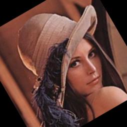
Rotates the image. First of all, the image is placed on a background canvas, then rotated with the centre of rotation specified, and finally cropped to its original dimensions. To those parts of final image that did not map from the area of the original image, color of canvas is assigned. It is possible to vary the values of rotation parameters as well as the background color in time, thus creating a dynamic rotation of the image. For further information, see Transform video filter.
The dialog allows to choose the type of interpolation used in inverse mapping. There are sliders in order to set the angle of rotation counterclockwise (in degrees), and the centre of rotation (in percentage of the distance from the centre of image to its edge); click on the color button to pick the color of the background canvas. If 'dynamic' box is checked, corresponding sliders plus a color button appear so that the rotation parameters as well as the color of background at the end of the clip can be set; the rate sliders affect the rate of variation of these values from the beginning to the end (when 'share rate' box is checked, these rates are shared and rate sliders move simultaneously).
The following table lists the filter's parameters in network file format.
Table 4.45. Rotate parameters
| Parameter | Values | Description | Required | Default value |
|---|---|---|---|---|
| videofilter | Transform | filter name | yes | |
| angle | real | angle of rotation counterclockwise [degrees] | no | 0 (no rotation) |
| angle_2 | real | angle of rotation counterclockwise [degrees] at the end | no | angle (constant rotation) |
| centre_x | real | centre of rotation, horizontal coordination [percentage of the distance from the centre of image to its edge] | no | 0 (centre of image) |
| centre_x_2 | real | centre of rotation, horizontal coordination [percentage of the distance from the centre of image to its edge] at the end | no | centre_x (constant position of centre) |
| centre_y | real | centre of rotation, vertical coordination [percentage of the distance from the centre of image to its edge] | no | 0 (centre of image) |
| centre_y_2 | real | centre of rotation, vertical coordination [percentage of the distance from the centre of image to its edge] at the end | no | centre_y (constant position of centre) |
| interpolation | "NN" or "bilinear" | type of interpolation used in reverse mapping [nearest neighbor or bilinear] | no | "bilinear" |
| color_R | real (0, 255) | value of red channel (RGB) in background color | no | 0 (black) |
| color_R_2 | real (0, 255) | value of red channel (RGB) in background color at the end | no | color_R (constant color channel) |
| color_G | real (0, 255) | value of green channel (RGB) in background color | no | 0 (black) |
| color_G_2 | real (0, 255) | value of green channel (RGB) in background color at the end | no | color_G (constant color channel) |
| color_B | real (0, 255) | value of blue channel (RGB) in background color | no | 0 (black) |
| color_B_2 | real (0, 255) | value of blue channel (RGB) in background color at the end | no | color_B (constant color channel) |
| rate | real > 0 | default rate of interpolation of dynamic parameters | no | 0 (linear interpolation) |
| rate_angle | real > 0 | rate of interpolation between angle and angle_2 | no | rate (shared rate) |
| rate_centre | real > 0 | rate of interpolation between centre and centre_2 | no | rate (shared rate) |
| rate_color | real > 0 | rate of interpolation between color_* and color_*_2 | no | rate (shared rate) |
The RGB mode is required, hence only the RGB24, RGBA32 and RGB32 formats are supported.
The algorithm must perform a lot of computations and therefore more
time is needed. For every image the ratios between the rotation parameters
and canvas color at the beginning (e.g., angle_x) and
at the end (e.g., angle_x_2) of the clip are figured
out, according to the rate_* parameters and the
relative position of the frame. Once the actual parameters are figured
out, the image is opened in one of RGB formats (see previous paragraph).
The algorithm just runs through the output image and for every pixel
counts its position in input image using inverse mapping. The output value
of the pixel is figured out from pixel values in a neighborhood of the
inversly mapped position in input image; selected interpolation process is
used. Note that the "pixels" outside the input image area share
the colors of background canvas; if RGBA32 format is used, alpha channel
is set to 255 (transparent).
The function Interpolate()interpolates the value
of the backwards mapped pixel from the values of pixels in the
neighborhood of its mapped position (usually somewhere between image
pixels). If interpolation = NN, just the value of the
nearest pixel is taken; for interpolation = bilinear
the value is counted as a weighted sum of values of the nearest four
pixels, the weights decreasing with the distance, their sum being equal to
one.
For example, angle = 0, angle_2 = 360,
centre_x = centre_y = 100 rotates the frames gradually
counterclockwise once around the lower right corner during the clip. A
special case of Transform, isn't it?
This filter simply sharpens the input image, i.e. boosts those pixels where intensity changes abruptly. Use with care - this procedure might also amplify the noise present in image.
The following table lists the filter's parameters in network file format.
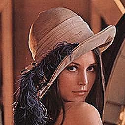
Translates the image. First of all, the image is placed on a background canvas, then shifted, and finally cropped to its original dimensions. To those parts of final image that did not map from the area of the original image, color of canvas is assigned. It is possible to vary the values of shift parameters as well as the background color in time, thus creating a dynamic movement of the image. For further information, see Transform video filter.
The dialog allows to choose the type of interpolation used in inverse mapping. There are sliders in order to set the length of shift (percentage of image dimensions); click on the color button to pick the color of the background canvas. If 'dynamic' box is checked, corresponding sliders plus a color button appear so that the shift parameters as well as the color of background at the end of the clip can be set; the rate sliders affect the rate of variation of these values from the beginning to the end (when 'share rate' box is checked, these rates are shared and rate sliders move simultaneously).
The following table lists the filter's parameters in network file format.
Table 4.50. Shift parameters
| Parameter | Values | Description | Required | Default value |
|---|---|---|---|---|
| videofilter | Shift | filter name | yes | |
| shift_x | real | length of shift in horizontal direction [percentage of image width] | no | 0 (no shift) |
| shift_x_2 | real | length of shift in horizontal direction [percentage of image width] at the end | no | shift_x (constant shift) |
| shift_y | real | length of shift in vertical direction [percentage of image width] | no | 0 (no shift) |
| shift_y_2 | real | length of shift in vertical direction [percentage of image width] at the end | no | shift_y (constant shift) |
| interpolation | "NN" or "bilinear" | type of interpolation used in reverse mapping [nearest neighbor or bilinear] | no | "bilinear" |
| color_R | real (0, 255) | value of red channel (RGB) in background color | no | 0 (black) |
| color_R_2 | real (0, 255) | value of red channel (RGB) in background color at the end | no | color_R (constant color channel) |
| color_G | real (0, 255) | value of green channel (RGB) in background color | no | 0 (black) |
| color_G_2 | real (0, 255) | value of green channel (RGB) in background color at the end | no | color_G (constant color channel) |
| color_B | real (0, 255) | value of blue channel (RGB) in background color | no | 0 (black) |
| color_B_2 | real (0, 255) | value of blue channel (RGB) in background color at the end | no | color_B (constant color channel) |
| rate | real > 0 | default rate of interpolation of dynamic parameters | no | 0 (linear interpolation) |
| rate_shift | real > 0 | rate of interpolation between shift and shift_2 | no | rate (shared rate) |
| rate_color | real > 0 | rate of interpolation between color_* and color_*_2 | no | rate (shared rate) |
The RGB mode is required, hence only the RGB24, RGBA32 and RGB32 formats are supported.
The algorithm must perform a lot of computations and therefore more
time is needed. For every image the ratios between the shift parameters
and canvas color at the beginning (e.g., shift_x) and
at the end (e.g., shift_x_2) of the clip are figured
out, according to the rate_* parameters and the
relative position of the frame. Once the actual parameters are figured
out, the image is opened in one of RGB formats (see previous paragraph).
The algorithm just runs through the output image and for every pixel
counts its position in input image using inverse mapping. The output value
of the pixel is figured out from pixel values in a neighborhood of the
inversly mapped position in input image; selected interpolation process is
used. Note that the "pixels" outside the input image area share
the colors of background canvas; if RGBA32 format is used, alpha channel
is set to 255 (transparent).
The function Interpolate()interpolates the value
of the backwards mapped pixel from the values of pixels in the
neighborhood of its mapped position (usually somewhere between image
pixels). If interpolation = NN, just the value of the
nearest pixel is taken; for interpolation = bilinear
the value is counted as a weighted sum of values of the nearest four
pixels, the weights decreasing with the distance, their sum being equal to
one.
For example, shift_y = -100, rate_shift
= 2 translates the frames from their original position upwards,
quickly at first, then slower and slower, until the frame disappears in
the end, the final frame of the color of background. A special case of
Transform, isn't it?
This filter is intended as a fast alternative to High-quality resize filter. It uses the inverse mapping algorithm with nearest-neighbour interpolation, which often introduces some aliasing artifacts. OpenVIP itself uses this filter to produce all preview images.
The dialog consists of two textfields - simply enter the new width and height.
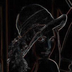
This filter attemps to find edges in the input image, where edge is a location where the pixel values change abruptly. It is possible to detect vertical or horizontal edges, or edges in all directions. (See also the Laplace edge detection filter.)
The dialog lets you choose the direction of edge detection - to detect all edges, check both horizontal and vertical options. The output image consists of bright contours on a dark background. However, there is another option called keep sign; it produces images which look like contours embossed in a piece of metal. Note that this option can be used only in combination with either horizontal or vertical edge detection (not both at the same time).
The following table lists the filter's parameters in network file format.
Table 4.53. Sobel parameters
| Parameter | Values | Description | Required | Default value |
|---|---|---|---|---|
| videofilter | Sobel | filter name | yes | |
| dir | vertical, horizontal, both | detect edges in the specified direction | yes | |
| keep_sign | boolean (0 or 1) | turn keep_sign off/on | no | 0 |
Sobel edge detection is a well-known algorithm based on convolution with the mask (-1 0 1) interpreted either as a column vector (detects horizontal edges), or as a row vector (vertical edges). The meaning of keep sign option is the same as with convolution plugin - with this option turned on, 127 will be added to every output pixel value; otherwise absolute values are used. The bidirectional version of edge detection proceeds as follows: First, it finds horizontal and vertical edges independently. Second, it sums the squares of these two images and finally returns the square root of the sum. This number is the length of a so-called digital gradient (a discrete approximation of the gradient vector of a scalar field).
This filter adds text subtitles (in MicroDVD format) to the videostream using the code from the FreeType 2 project.
The Subtitle file and the Font file
fields are (unsurprisingly) for specifying the path to files with
subtitles and used font respectively. In the Encoding
field you can choose between three possible character encodings:
iso-8859-1, iso-8859-2 and
windows-1250. The Font size field
is self-explanatory, as is the Align field (left,
center or right).
Bottom space determines how many pixels are left
between the bottom line of the subtitle box and the bottom line of the
whole image. And Transparency sets how transparent
the box around subtitles will be (in percents - 0 means solid black, 100
means not visible at all).
The following table lists the filter's parameters in network file format.
Table 4.55. Subtitle parameters
| Parameter | Values | Description | Required | Default |
|---|---|---|---|---|
| filename | string | an existing filename | yes | |
| font | string | an existing filename | yes | |
| align | string: left, center
or right | self-explanatory | no | center |
| font_size | postitive integer | self-explanatory | no | 12 |
| bottom | positive integer | space left under the subtitle box | no | 20 |
| encoding | string: iso-8859-1, iso-8859-2
or windows-1250 | character encoding | no | windows-1250 |
| alpha | real number between 0 and 1 | transparency of the subtitle box | no | 0.5 |
The plugin has been tested with TrueType fonts. It may work with other kinds of fonts as well but it is untested and the results might be unsatisfactory.
The support for international characters is currently limited only to Czech national characters and only with fonts that provide character names.
Creates a "binary" image with values distributed according to the threshold parameter; pixels with values below the threshold ("dark") are assigned one value (e.g., black) while those above the threshold ("light") are set to antoher value (e.g., white). It is possible to vary the threshold as well as the output brightness of both dark and light values in time, thus reflecting dynamic changes in the clip. The threshold can be compared either to data from a selection of RGB color channels [2] or to the brightness channel in either YUV or HSV color format. The output brightness for dark and light values may also be applied either to data from a selection of RGB color channels [2] or to the brightness channel in either YUV or HSV color format. Threshold is a useful tool for image data preprocessing in, e.g., computer vision or biology because it is able to emphasize examined structures whereas it significantly reduces the amout of data. Enhanced threshold or posterize filters are also often used video industry or modern art (think of white faces with black eyes, lips and hair).
The dialog allows to switch between RGB, YUV and HSV image formats for input data (compared with threshold) and, for RGB, to choose color channels (R...red, G...green, B...blue) that will be used. Indepently of this, RGB, YUV or HSV image format for output data ("thresheld") can be selected, and, for RGB, the color channels (R...red, G...green, B...blue) that will be affected. The RGB mode employs only selected RGB channels, while the other ones use just the intensity channel (Y in YUV or V in HSV). There are three sliders in order to set the threshold and the values used for dark and light values, their scale in percentage of brightness intensity. If 'dynamic' box is checked, corresponding sliders appear so that the threshold and both dark and light values at the end of the clip could be set; the rate sliders affect the rate of variation of these values from the beginning to the end (when 'share rate' box is checked, these rates are shared and move simultaneously).
The following table lists the filter's parameters in network file format.
Table 4.57. Threshold parameters
| Parameter | Values | Description | Required | Default value |
|---|---|---|---|---|
| videofilter | Threshold | filter name | yes | |
| format_in | RGB, YUV, HSV | image format of input data (to be thresheld) | no | RGB |
| channel_R_in | boolean (0 or 1) | include red channel in input data (RGB) | no | 1 |
| channel_G_in | boolean (0 or 1) | include green channel in input data (RGB) | no | 1 |
| channel_B_in | boolean (0 or 1) | include green channel in input data (RGB) | no | 1 |
| format_out | RGB, YUV, HSV | image format of output data (thresheld) | no | RGB |
| channel_R_out | boolean (0 or 1) | modify red channel in output data (RGB) | no | 1 |
| channel_G_out | boolean (0 or 1) | modify green channel in output data (RGB) | no | 1 |
| channel_B_out | boolean (0 or 1) | modify blue channel in output data (RGB) | no | 1 |
| threshold | real (0, 256) | threshold value | no | 128 (mid-gray) |
| threshold_2 | real (0, 256) | threshold value at the end | no | threshold (constant threshold) |
| dark | real (0, 255) | output brightness for values below threshold | no | 0 (black) |
| dark_2 | real (0, 255) | output brightness for values below threshold at the end | no | dark (constant value) |
| light | real (0, 255) | output brightness for values above threshold | no | 255 (white) |
| light_2 | real (0, 255) | output brightness for values above threshold at the end | no | light (constant value) |
| rate | real (-1, 1) | default speed of interpolation of dynamic parameters | no | 0 (linear interpolation) |
| rate_threshold | real (-1, 1) | speed of interpolation between threshold and threshold_2 | no | rate (shared rate) |
| rate_dark | real (-1, 1) | speed of interpolation between dark and dark_2 | no | rate (shared rate) |
| rate_light | real (-1, 1) | speed of interpolation between light and light_2 | no | rate (shared rate) |
The RGB mode can operate on images in any of RGB24, RGBA32 and RGB32 formats. The YUV mode requests YV12 format. This format, however, supports only images with even dimensions so when either the width or the height of input image are of odd dimension, image is opened in RGB format, broadened to even dimensions, converted to YV12 format, processed, converted to RGB format again and finally cropped to its original dimensions. In HSV mode HSV24 format is used.
The algorithm may seem complicated, but only just because of the
possibility of different format_in and
format_out. For every image the ratios between the
threshold values and the values for dark and light pixels at the beginning
and at the end of the clip are figured out, according to the
rate_* parameters and the relative position of the
frame. The image is opened in a format supported by format_out
(or simulated when format_out = YUV and the image has
odd dimensions, as described in the previous paragraph). However, if
format_out = YUV or HSV, and
different from format_in, a copy of image in one of
RGB formats must be created. The algorithm just runs
through the image (or the copy when there is one) and for every pixel
counts its intensity as an average of its values in all channels specified
by format_in and channel_*_in. If
there's a copy in RGB and format_in = YUV,
the intensity is counted as a weighted sum of RGB channels with the same
weights as in the definition of YUV format; for format_in = HSV
maximal value across RGB channels is taken. This intensity of pixel is
then compared with the threshold - if smaller,
dark value is assigned to all channels specified by
format_out and channel_*_out in the
image (not the copy); otherwise, light value is
assigned. Other channels retain their original values. If
format_in = RGB and none of channel_*_in
parameters is true, threshold is
automaticly set to 256 ( and therefore all pixels are
set to dark).
For example, format_out = HSV results in an image
with all "dark" pixels set to black while the brightness of all
"light" pixels is set to maxima; thus a cartoon-like effect of
bright pastel colors in contrast with black areas is produced. So complex
yet so simple, isn't it?
Applies one or more geometric transformations to the image. First of all, the image is placed on a background canvas, then zoomed with the centre of the zoom specified, afterwards rotated around this centre, shifted, and finally cropped to its original dimensions. To those parts of final image that did not map from the area of the original image, color of canvas is assigned. It is possible to vary the values of transformation parameters as well as the background color in time, thus creating a dynamic movement of the image. Geometric transformations, especially zoom, rotation and translation (i.e., shift), are often used in, e.g., digital image processing, in order to remove geometric deviations of the scanning device and thus retreive a more true image of the original object. Transform is also a sufficient tool for most geometric transformations used in video animations.
The dialog allows to choose the type of interpolation used in inverse mapping. There are sliders for each type of transformation in order to set the relative zoom factor (with logarithmic scale), angle of rotation counterclockwise (in degrees), the centre of zoom and rotation (in percentage of the distance from the centre of image to its edge), and the length of shift (percentage of image dimensions); click on the color button to pick the color of the background canvas. If 'dynamic' box is checked, corresponding sliders plus a color button appear so that the transformation parameters as well as the color of background at the end of the clip can be set; the rate sliders affect the rate of variation of these values from the beginning to the end (when 'share rate' box is checked, these rates are shared and rate sliders move simultaneously).
The following table lists the filter's parameters in network file format.
Table 4.59. Transform parameters
| Parameter | Values | Description | Required | Default value |
|---|---|---|---|---|
| videofilter | Transform | filter name | yes | |
| zoom_x | real > 0 | zoom ratio in horizontal direction | no | 1 (no zoom) |
| zoom_x_2 | real > 0 | zoom ratio in horizontal direction at the end | no | zoom_x (constant zoom) |
| zoom_y | real > 0 | zoom ratio in vertical direction | no | 1 (no zoom) |
| zoom_y_2 | real > 0 | zoom ratio in vertical direction at the end | no | zoom_y (constant zoom) |
| angle | real | angle of rotation counterclockwise [degrees] | no | 0 (no rotation) |
| angle_2 | real | angle of rotation counterclockwise [degrees] at the end | no | angle (constant rotation) |
| centre_x | real | centre of zoom and rotation, horizontal coordination [percentage of the distance from the centre of image to its edge] | no | 0 (centre of image) |
| centre_x_2 | real | centre of zoom and rotation, horizontal coordination [percentage of the distance from the centre of image to its edge] at the end | no | centre_x (constant position of centre) |
| centre_y | real | centre of zoom and rotation, vertical coordination [percentage of the distance from the centre of image to its edge] | no | 0 (centre of image) |
| centre_y_2 | real | centre of zoom and rotation, vertical coordination [percentage of the distance from the centre of image to its edge] at the end | no | centre_y (constant position of centre) |
| shift_x | real | length of shift in horizontal direction [percentage of image width] | no | 0 (no shift) |
| shift_x_2 | real | length of shift in horizontal direction [percentage of image width] at the end | no | shift_x (constant shift) |
| shift_y | real | length of shift in vertical direction [percentage of image width] | no | 0 (no shift) |
| shift_y_2 | real | length of shift in vertical direction [percentage of image width] at the end | no | shift_y (constant shift) |
| interpolation | "NN" or "bilinear" | type of interpolation used in reverse mapping [nearest neighbor or bilinear] | no | "bilinear" |
| color_R | real (0, 255) | value of red channel (RGB) in background color | no | 0 (black) |
| color_R_2 | real (0, 255) | value of red channel (RGB) in background color at the end | no | color_R (constant color channel) |
| color_G | real (0, 255) | value of green channel (RGB) in background color | no | 0 (black) |
| color_G_2 | real (0, 255) | value of green channel (RGB) in background color at the end | no | color_G (constant color channel) |
| color_B | real (0, 255) | value of blue channel (RGB) in background color | no | 0 (black) |
| color_B_2 | real (0, 255) | value of blue channel (RGB) in background color at the end | no | color_B (constant color channel) |
| rate | real > 0 | default rate of interpolation of dynamic parameters | no | 0 (linear interpolation) |
| rate_zoom | real > 0 | rate of interpolation between zoom and zoom_2 | no | rate (shared rate) |
| rate_angle | real > 0 | rate of interpolation between angle and angle_2 | no | rate (shared rate) |
| rate_centre | real > 0 | rate of interpolation between centre and centre_2 | no | rate (shared rate) |
| rate_shift | real > 0 | rate of interpolation between shift and shift_2 | no | rate (shared rate) |
| rate_color | real > 0 | rate of interpolation between color_* and color_*_2 | no | rate (shared rate) |
The RGB mode is required, hence only the RGB24, RGBA32 and RGB32 formats are supported.
The algorithm must perform a lot of computations and therefore more
time is needed. For every image the ratios between the transformation
parameters and canvas color at the beginning (e.g., shift_x)
and at the end (e.g., shift_x_2) of the clip are
figured out, according to the rate_* parameters and the
relative position of the frame. Once the actual parameters are figured
out, the image is opened in one of RGB formats (see previous paragraph).
The algorithm just runs through the output image and for every pixel
counts its position in input image using inverse mapping. The output value
of the pixel is figured out from pixel values in a neighborhood of the
inversly mapped position in input image; selected interpolation process is
used. Note that the "pixels" outside the input image area share
the colors of background canvas; if RGBA32 format is used, alpha channel
is set to 255 (transparent).
As the image is first zoomed, then rotated and finally shifted, the
inverse-mapping function MapInverse() does these
operations in reversed order (let's suppose that the centre of image
is in [0,0]):
1. Shift back: [x,y] = [x - shift_x, y - shift_y]
2. Translate the centre of image to [0,0]: [x, y] = [x -
centre_x, y - centre_y]
3. Rotate the image clockwise (angle in radians):
[x,y] = [x*cos(angle) - y*sin(angle), x*sin(angle) +
    y*cos(angle)]
4. Zoom with inverse zoom factor: [x,y] = [x / zoom_x, y /
zoom_y]
5. Translate the center of image back from [0,0]:
[x,y] = [x + centre_x, y + centre_y]
The function Interpolate()interpolates the value
of the backwards mapped pixel from the values of pixels in the
neighborhood of its mapped position (usually somewhere between image
pixels). If interpolation = NN, just the value of the
nearest pixel is taken; for interpolation = bilinear
the value is counted as a weighted sum of values of the nearest four
pixels, the weights decreasing with the distance, their sum being equal to
one.
For example, zoom_x = zoom_y = 2 setting zooms
the image twice, angle = 0, angle_2 = 360
rotates the frames gradually counterclockwise once around during the clip,
shift_x = 50, rate_shift = 0.5
translates the frames from their original position to the right, first
slowly, then more and more quickly, until only a half of the original
frame is visible, the left half with the color of background. It's
great, isn't it?
Zooms to the image. First of all, the image is placed on a background canvas, then zoomed with the centre of the zoom specified, and finally cropped to its original dimensions. To those parts of final image that did not map from the area of the original image, color of canvas is assigned. It is possible to vary the values of zoom parameters as well as the background color in time, thus creating a dynamic zoom of the image. For further information, see Transform video filter.
The dialog allows to choose the type of interpolation used in inverse mapping. There are sliders in order to set the relative zoom factor (with logarithmic scale), and the centre of zoom (in percentage of the distance from the centre of image to its edge); click on the color button to pick the color of the background canvas. If 'dynamic' box is checked, corresponding sliders plus a color button appear so that the zoom parameters as well as the color of background at the end of the clip can be set; the rate sliders affect the rate of variation of these values from the beginning to the end (when 'share rate' box is checked, these rates are shared and rate sliders move simultaneously).
The following table lists the filter's parameters in network file format.
Table 4.61. Zoom parameters
| Parameter | Values | Description | Required | Default value |
|---|---|---|---|---|
| videofilter | Transform | filter name | yes | |
| zoom_x | real > 0 | zoom ratio in horizontal direction | no | 1 (no zoom) |
| zoom_x_2 | real > 0 | zoom ratio in horizontal direction at the end | no | zoom_x (constant zoom) |
| zoom_y | real > 0 | zoom ratio in vertical direction | no | 1 (no zoom) |
| zoom_y_2 | real > 0 | zoom ratio in vertical direction at the end | no | zoom_y (constant zoom) |
| centre_x | real | centre of zoom, horizontal coordination [percentage of the distance from the centre of image to its edge] | no | 0 (centre of image) |
| centre_x_2 | real | centre of zoom, horizontal coordination [percentage of the distance from the centre of image to its edge] at the end | no | centre_x (constant position of centre) |
| centre_y | real | centre of zoom, vertical coordination [percentage of the distance from the centre of image to its edge] | no | 0 (centre of image) |
| centre_y_2 | real | centre of zoom, vertical coordination [percentage of the distance from the centre of image to its edge] at the end | no | centre_y (constant position of centre) |
| interpolation | "NN" or "bilinear" | type of interpolation used in reverse mapping [nearest neighbor or bilinear] | no | "bilinear" |
| color_R | real (0, 255) | value of red channel (RGB) in background color | no | 0 (black) |
| color_R_2 | real (0, 255) | value of red channel (RGB) in background color at the end | no | color_R (constant color channel) |
| color_G | real (0, 255) | value of green channel (RGB) in background color | no | 0 (black) |
| color_G_2 | real (0, 255) | value of green channel (RGB) in background color at the end | no | color_G (constant color channel) |
| color_B | real (0, 255) | value of blue channel (RGB) in background color | no | 0 (black) |
| color_B_2 | real (0, 255) | value of blue channel (RGB) in background color at the end | no | color_B (constant color channel) |
| rate | real > 0 | default rate of interpolation of dynamic parameters | no | 0 (linear interpolation) |
| rate_zoom | real > 0 | rate of interpolation between zoom and zoom_2 | no | rate (shared rate) |
| rate_centre | real > 0 | rate of interpolation between centre and centre_2 | no | rate (shared rate) |
| rate_color | real > 0 | rate of interpolation between color_* and color_*_2 | no | rate (shared rate) |
The RGB mode is required, hence only the RGB24, RGBA32 and RGB32 formats are supported.
The algorithm must perform a lot of computations and therefore more
time is needed. For every image the ratios between the zoom parameters and
canvas color at the beginning (e.g., centre_x) and at
the end (e.g., centre_x_2) of the clip are figured out,
according to the rate_* parameters and the relative
position of the frame. Once the actual parameters are figured out, the
image is opened in one of RGB formats (see previous paragraph). The
algorithm just runs through the output image and for every pixel counts
its position in input image using inverse mapping. The output value of the
pixel is figured out from pixel values in a neighborhood of the inversly
mapped position in input image; selected interpolation process is used.
Note that the "pixels" outside the input image area share the
colors of background canvas; if RGBA32 format is used, alpha channel is
set to 255 (transparent).
The function Interpolate()interpolates the value
of the backwards mapped pixel from the values of pixels in the
neighborhood of its mapped position (usually somewhere between image
pixels). If interpolation = NN, just the value of the
nearest pixel is taken; for interpolation = bilinear
the value is counted as a weighted sum of values of the nearest four
pixels, the weights decreasing with the distance, their sum being equal to
one.
For example, zoom_x = zoom_y = 1, zoom_x_2 = zoom_y_2 = 10,
centre_x_2 = centre_y_2 = -100 setting gradually zooms the image
ten times to the upper left corner. A special case of Transform, isn't
it?
